Summary Statement
A study designed to measure slip-resistant paints for structural steel in order to prevent falls by structural steel erectors.
1995
William English is a self-employed safety engineering consultant who has had extensive experience in fall accident investigation and has, in fact, worked as an ironworker in his pre-college days. He is a registered Professional (Safety) Engineer and a Certified Safety Professional. He is active on the ASTM (American Society for Testing and Materials) F-13 Committee on Safety and Traction for Footwear, as well as ANSI (American National Standards Institute) Committees Z359 on Safety Requirements for Personal Fall Arrest Systems and A1264.2 on Slip Resistance Measurement. The author is also active on other ASTM and ANSI committees having to do with fall prevention and slip-resistance measurement, and he holds patents on slipmeter technology.
William Marletta is a self-employed safety consultant heavily engaged in the investigation of falling accidents and safety engineering means of preventing them. His doctoral thesis involved technical evaluation of current slipmeters, including the two used for the tests reported here. He is chairman of the ASTM F-13 Committee on Safety and Traction for Footwear and is active on the ANSI A1264.2 Committee on Slip Resistance. His professional designations include a Ph.D. in Occupational Safety and Health from New York University, Certified Safety Professional, and Certified Hazard Control Manager; and he is a member of other ASTM and ANSI committees dealing with fall prevention and the measurement of slip resistance.
Background
Project Design
Materials Used
Testing Conditions
Slipmeter Testing
- Measurements
- Observations During Testing
- Results
Ironworkers' Subjective Rankings of Surfaces
- Methods and Participants
- Results
Discussion
of Findings
Wording
For a Proposed Rule
Conclusion
Bibliography
Tables
- Surfaces tested
- Slipmeter test results using Brungraber, Mark II, and English XL meters
- Ironworker rankings of surface slip resistance
Figure
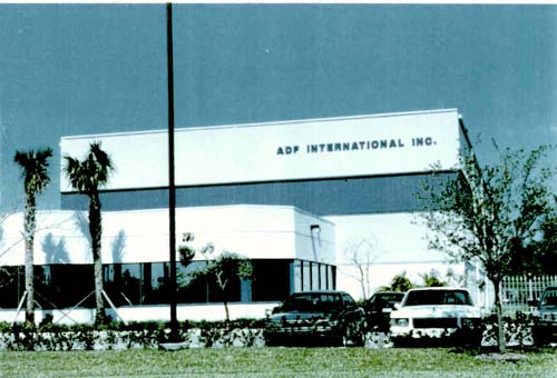
1. All testing was done at ADF International, Inc., facilities in Coral
Springs, Florida.
Figure 2. Experimental paints were all applied by brushing
by an ADF employee.
Figure 3. Atmospheric conditions were monitored at the
time of testing.
Figure 4. All test surfaces were approximately level, well
within the range permitted for using the Brungraber, Mark II
Figure 5. Small pieces were a bit more difficult to meter.
Figure 6. Both testers were operated under both wet and
dry conditions.
Figure 7. All test walkers were carefully instructed in
order to maximize objectivity and comparability of their opinions.
Figure 8. All walking tests were conducted under wet conditions.
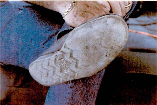
Figure 9. Shoe bottoms were prepared by sanding to remove
surface deposits and provide uniformity of surface finish.
Figure 10. Steve Cooper, safety director of the Iron Workers
International Union, assists William Marletta by wetting the surface for
the English XL on surface F.
Figure 11. The ironworker participants wore their customary
work boots.
Figure 12. Contamination was removed from the bottoms
by sanding.
Figure 13. All shoes were fairly well-worn.
Figure 14. Two walkers wore the same pair of shoes.
In an effort to assist the Occupational Safety and Health Administration (OSHA) in development of a specification for a safe level of slip resistance on structural steel, the International Association of Bridge, Structural and Ornamental Iron Workers obtained funding from CPWR – Center for Construction Research and Training to engage the services of William English and William Marletta to investigate three issues: valid means of measuring slip-resistance performance of painted surfaces, the feasibility of establishing a threshold of safety, and subjective verification of the means of measuring compliance with the specification.
Of course, experienced safety engineers have long recognized that fall accident rates tend to be dramatically underreported, because people completing the original injury reports often do not have safety engineering backgrounds and therefore are not competent at coding accidents by type. Many incidents reported as "struck against" or "contact with" are secondary accidents that were initiated by slips, which may not be recorded in the report or discerned by the input-coding operative. Therefore, the actual fall hazard is believed to be much worse than published statistics indicate.
The seriousness of the slip or fall hazard is well recognized in the erection industry. Experienced ironworkers know of major injuries and deaths that have resulted from slippery steel surfaces, and many of them report having had near-miss occurrences, where they slipped but were able to recover before actually falling.
Because of the high-severity potential of falls as an accident type and their prevalence among ironworkers working at elevations, the Steel Erection Negotiated Rule making Advisory Committee (SENRAC) began an investigation of possible solutions to this recognized problem.
Following a presentation by William English to the February 8, 1995 SENRAC meeting on the physics of slipping and the state of the art in slip-resistance measurement, meeting participants asked him to demonstrate the feasibility of setting a standard for the slip resistance of structural steel and to propose wording for a performance specification for inclusion in the OSHA 1926 rule making.
- Painted surfaces can be made slip-resistant.
- Slip resistance can be measured with state-of-the-art slipmeters.
- A reasonable threshold of safety can be established.
- Empirical field evaluations by ironworkers would validate the demonstrated measurement methodology.
The ironworkers were to participate in establishment of the safety threshold. That is, the consultants would demonstrate that they can quantify the slipperiness of steel structural forms using instruments and the ironworkers would tell them whether the meter indications accurately reflected their perceptions. The ironworkers would also determine what degree of slip-resistance they regarded as reasonably safe for them to walk on under wet conditions at elevation.
This was not an effort to study the slip-resistance performance of any particular paint, but was to show the feasibility of achieving and measuring compliance with a specified threshold of safe slip resistance.
Seven combinations of paint and steel were prepared for testing (table 1). The powder additive added texture.
| Table 1. Surfaces tested | ||
| Surface | Paint | Steel |
| A | Carbozinc green 0300 w/ a zinc powder additive | 10"-wide, flange H-beam |
| B | Carboline 858 w/ a zinc powder additive | 10"-wide, flange H-beam |
| C | Perry & Derrick parts 95093 & 75798 w/ a powder additive | 10"-wide, flange H-beam |
| D | Sherwin Williams Zinc Clad w/ powder additive | Galvanized corrugated decking |
| E | Smooth, glossy | Corrugated decking, factory painted |
| F | S. L. Gillman red oxide primer P1476S | Square tube, c. 8" wide, spray-painted by shop |
| G | Unpainted, pristine mill finish | 10"-wide, flange H-beam (w/ no visible rust). |
Five of the paint finishes were brushed on by an ironworker employee of ADF the day before the test; surface E had been factory painted and surface F had been spray-painted earlier by the shop as part of a fabrication order. Manufacturers' instructions had specified spray application of the experimental coatings (A, B, and C), but the paints clogged the available spray equipment. The brush-painting option was chosen in order to meet the project deadline.
All tests were performed outdoors under a shed roof adjoining ADF's fabrication shop building in Coral Springs, Florida. Ambient atmospheric conditions of 78 degrees Farenheit and the relative humidity of 80% were recorded before testing was begun.
Measurements
Slip resistance testing began on May 9, 1995, starting at about 10:00 a.m. Marletta performed all of the slipmeter testing using two types of instruments: a Brungraber, Mark II, and an English XL. Both devices are subjects of draft standards now in the full-committee ballot phase of ASTM F-13 (Safety and Footwear Traction.) Testing methods employed procedures set forth in the latest draft standards and manufacturers' instructions.
The English XL tester was operated at a working pressure of 25 psi (pounds per square inch).
The slider pads on both meters were of the standard test grade of Neolite as supplied by their manufacturers. The pads were prepared by sanding with 400-grit silicon carbide paper, and both the slider pads and the test surfaces were blown off with shop-compressed air. During the dry testing, the pads were resurfaced by sanding and blown off with compressed air each time the pad slipped.
Slipperiness indications were taken in two opposite directions on each surface, because the shapes of the beams and panels made it difficult to position the meters to obtain transverse measurements. Test results show the paired readings as "east" and "west," designating the opposing directions (table 2).
After dry measurements were taken and recorded, the same surfaces were metered under wet conditions. An unbroken film of water was applied to each surface before each meter stroke, using manually pumped spray bottles, and results were recorded.
Observations During Testing
Some difficulty was experienced while attempting to meter the two decking panels because of the corrugated shape and the poor rigidity of the small pieces used as test specimens. Some shimming of slipmeter feet was required to position them on the same plane as the smaller test surfaces, and an effort was made to support them in a relatively rigid state.
Aside from the minor difficulty in positioning the meters on these small complex shapes, dry testing was uneventful and routine. The two meters were in approximate agreement on the ranking of the traction performance of the test samples.
During wet testing, it was observed that the water applied to the surface tended to bead up and not flow smoothly on surfaces A, E, and F. Also, the friction of the slider pads striking the surfaces caused visible wear on some coatings, requiring the meters to be moved regularly to new areas to obtain consistent readings, particularly on surfaces D and F (see Discussion of Findings, below).
Results
Four readings were taken on each surface, two in dry and two in wet conditions. All indications were recorded to two decimal places and, in averaging, numbers were rounded to the nearest hundredth.
| Table 2. Slipmeter test results using Brungraber, Mark II, and English XL meters | ||||||
| Dry | Wet | |||||
| Surface | East | West | Average | East | West | Average |
| Brungraber, Mark II | ||||||
| A | .82 | .82 | .82 | .73 | .74 | .74 |
| B | .84 | .85 | .85 | .56 | .61 | .59 |
| C | .87 | .87 | .87 | .75 | .69 | .72 |
| D | .65 | .60 | .63 | .56 | .53 | .55 |
| E | .73 | .62 | .68 | .14 | .13 | .14 |
| F | .75 | .77 | .76 | .54 | .47 | .51 |
| G | .72 | .74 | .73 | .16 | .33 | .25 |
| English XL | ||||||
| A | .94 | .96 | .95 | .83 | .82 | .83 |
| B | .89 | .89 | .89 | .74 | .75 | .75 |
| C | .90 | .89 | .90 | .92 | .88 | .90 |
| D | .70 | .67 | .69 | .60 | .63 | .62 |
| E | .73 | .74 | .74 | .17 | .11 | .14 |
| F | .77 | .79 | .78 | .35 | .32 | .34 |
| G | .82 | .83 | .83 | .34 | .29 | .32 |
After slipmeter measurements were conducted on the test surfaces, five ironworkers wearing work shoes walked on the seven wet surfaces and ranked them in order of slipperiness. Before walking, the participants were instructed to concentrate on how the surfaces felt under foot and to disregard other factors, such as appearance. They were also instructed to repeat their comparative evaluations as often as necessary to reach carefully considered ranking judgments. That is, they could go back and forth among the test surfaces as often as needed to form an opinion, but they were instructed not to discuss their opinions with other participants who had not yet performed their evaluations. A copy of the instructions to the walkers appears in the appendix.
Just before each participant walked on the test surfaces (whenever a participant's shoes touched the ground), his shoe bottoms were sanded with 400-grit paper and were blown off with compressed air. The shoe bottoms were also sprayed with water before the walks began. The walking tests were performed only under wet conditions.
The participants were:
- Bruce Weber, 10 years' experience as an ironworker
- Robert Stack, more than 35 years
- Steve Cooper, 35 years
- Dewey Tyler, 15 years
- Roy Burns, 23 years.
The soles of the shoes worn by Weber (1) and Burns (5) were Neoprene based, while the other three pairs were crepe.
Results
The five walkers ranked the surfaces in order from most to least slip-resistant (table 3).
| Table 3. Ironworker rankings of surface slip resistance | |||||||
| Ironworker |
Slip
resistance ranking
|
||||||
| Most | Least | ||||||
| 1 | C | A | B | D | G | E | F |
| 2 | C | A | B | D | G | E | F |
| 3 | C | A | B | D | G | E | F |
| 4 | C | A | B | D | G | F | E |
| 5 | C | D | A | B | G | E | F |
After each participant had graded the seven surfaces for slip resistance, he was then asked which surfaces were sufficiently slip-resistant to be safe. Each beam walker was asked his opinion as to where the threshold of safety would be among the seven surfaces tested. The consensus was that the top-rated three (C, A, and B) were adequate, but one participant thought only the best rating was good enough. Two participants thought that, in addition, the fourth-rated surface was adequate.
During wet testing, at the levels of slip-resistance that the ironworkers generally considered to be satisfactory, the Mark II instrument tended to give lower indications than the XL tester. There are two plausible explanations for these differences in indications. One is that the much larger area of surface contact (the Mark II shoe having nearly 10 times the area of the XL shoe) would be expected to have a more pronounced hydroplane effect on the water film. The other is that the flat contact attitude of the Mark II as contrasted with the "heel-first" contact attitude of the XL would be expected to contribute further to a slipperier indication for the larger device.
The correspondence of the slipmeter indications with the subjective rankings of the ironworkers confirms the notion that the relative safety of structural steel under wet conditions, such as is often encountered in early mornings on typical open-air work sites, can be measured. Further, there was agreement among both slipmeters and all ironworkers interviewed that all of the dry surfaces were not slippery.
Both the slipmeter results and the ironworker walking evaluations confirmed that ordinary red oxide primer painted steel (as applied to surface F) is extremely slippery when wet, as was the smooth, glossy paint finish routinely applied to the steel corrugated decking (designated E in our tests.)
The small size of panel E made it difficult to walk on in the same manner as on the larger surfaces; this factor may account for why the walkers rated it as considerably less slippery than the meters did.
|
Slip-Resistance of Structural Steel All structural
steel parts that can foreseeably be walked on by field erection
personnel at elevations above grade level shall have a finish that
is slip-resistant under wet conditions, using a standard Neolite
slider pad on a surface that is wet with an unbroken film of water. |
Of course, other contaminants are so slippery as to be difficult to protect against adequately by paint finish; these include mineral oil and some kinds of mud. But the use of slip-resistant finishes on structural components can enhance the safety of erector personnel considerably by providing reasonable protection against slipping under the most commonly occurring hazardous conditions produced regularly by rain and dew.
The level of slip resistance suggested by the consensus of the ironworkers is warranted for two reasons. First, the extreme hazard inherent in high work elevations demands a high slip resistance performance. Second, the mandated level of traction performance is readily achievable in paints now available.2
1Footwear is also an important factor in ironworker fall protection, but is beyond the scope of this project. There are facilities for objectively evaluating and ranking footwear, which may be employed in future investigations.
The consultants and ironworkers participating in this study strongly believe that implementation of this minimum slip resistance rule would save lives. Ironworkers would not be the only beneficiaries of the improved foot traction, because other crafts are also required to walk on the structural surfaces following erection; increased safety among workers in other allied trades would be realized as well.
Although there may be initial resistance from some affected segments of the construction industry, because compliance with the proposed performance specification will require changes in materials, equipment, and application procedure, the lives saved will be well worth the required modifications.
English, William. Slips, Trips and Falls: Safety Engineering Guidelines for the Prevention of Slip, Trip and Fall Occurrences. Hanrow Press, Inc., P. O. Box 847, Del Mar, Calif. 92014, 1989.
Marletta, William. The Effects of Humidity and Wetness on Pedestrian Slip Resistance Evaluated with Slip Testing Devices on Selected Sole and Floor Surface Materials, Submitted in partial fulfillment of the degree of Doctor of Philosophy, School of Education, New York University, 1994.
Occupational Safety and Health Administration (OSHA), Federal Register, Vol. 55, No. 69, Tuesday, April 10, 1990, Proposed Rules.
Zeischang, Kimberly D., report to Thomas J. Shepich, Director, Directorate of Safety Standards Programs (OSHA), on "Work Related Injuries and Illnesses to Structural Metal Workers," 12/20/90.
Figure
1. All testing was done at ADF International, Inc., facilities in Coral
Springs, Florida.
Figure
2. Experimental paints were all applied by brushing by an ADF employee.
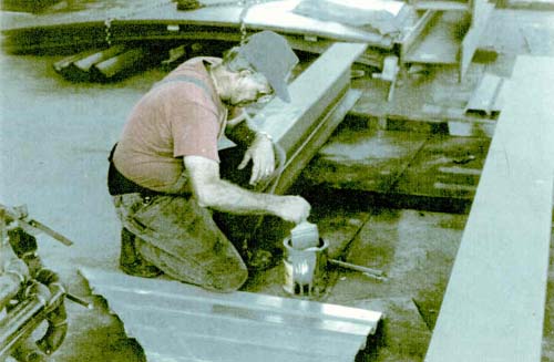
Figure 3. Atmospheric conditions were monitored at the time of testing.
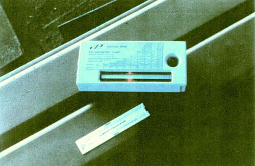
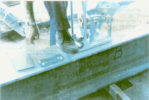
Figure 5. Small pieces were a bit more difficult to meter.
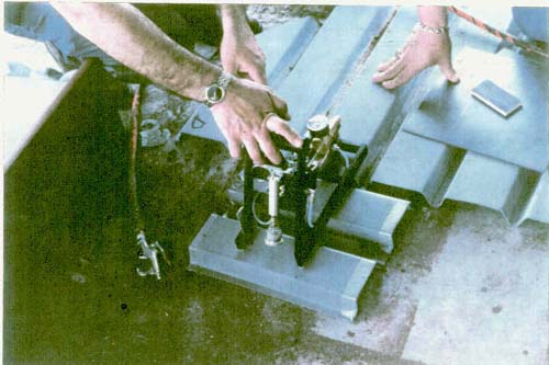
Figure 6. Both testers were operated under both wet and dry conditions.
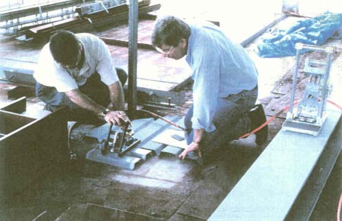
Figure 7. All test walkers were carefully instructed in order to maximize objectivity and comparability of their opinions.
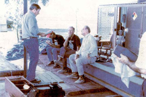
Figure 8. All walking tests were conducted under wet conditions.
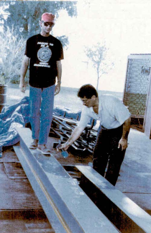
Figure 9. Shoe bottoms were prepared by sanding to remove surface deposits and provide uniformity of surface finish.
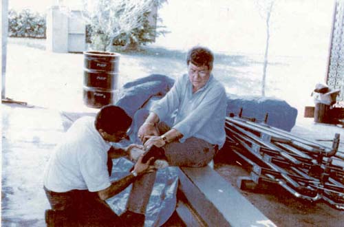
Figure 10. Steve Cooper, safety director of the Iron Workers International Union, assists William Marletta by wetting the surface for the English XL on surface F.
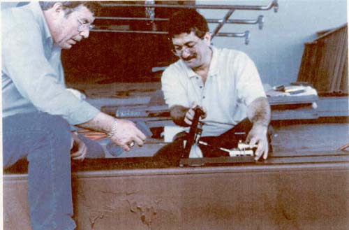
Figure 11. The ironworker participants wore their customary work boots.
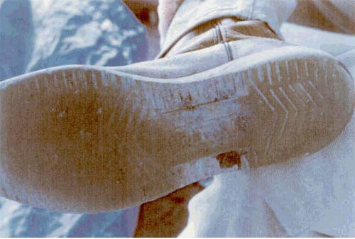
Figure 12. Contamination was removed from the bottoms by sanding.
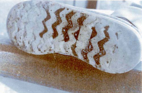
Figure 13. All shoes were fairly well-worn.
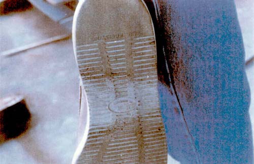
Figure 14. Two walkers wore the same pair of shoes.