
Summary Statement
On June 10, 2009, three construction employees were killed when a mast climbing platform collapsed at a condominium project under construction in Austin, Texas. This is the engineering investigation report generated by OSHA's Directorate of Construction.
December 2009
U.S. Department of Labor
Occupational Safety and Health Administration
Directorate of Construction
December 2009
Report Prepared by:
Mohammad Ayub, P.E., S.E.
Contributions to this report made by:
Gopal Menon, P.E., Office of Engineering Services, DOC, OSHA National Office
Michael P. Jarvis, Safety Compliance Officer, OSHA Austin Area Office
Introduction
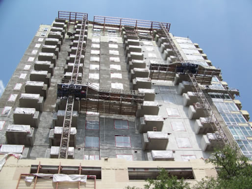
On June 10, 2009, at about 2:20 p.m., three construction employees of Capoera Construction, LLC of Margate, FL were killed when a mast climbing platform north of the mast collapsed at a condominium project under construction in Austin, Texas. The platform south of the mast and the mast itself remained intact and did not collapse. The site where the accident occurred was located at 2101 Rio Grande, Austin, Texas. At the time of the collapse, about eight employees including the operator were located on both sides of the platform. Immediately before the incident, the platform descended from the13th floor and was stopped at the eleventh floor when the north platform suddenly separated from the main frame (motorized unit) and the mast, and fell to the seventh floor. As a result of the failure, three employees fell with the platform. Two of them fell 11 stories to the ground and the third fell to the seventh floor. The other two employees on the north side were able to hold onto the balcony and were saved.
Description of the Project
The project consisted of a 21-story concrete framed condominium building. Merriman Associates of Dallas, TX was the architect and L.A. Fuess Partners, Inc. of Dallas, TX was the structural engineer of record. Andres Construction of Dallas, TX was the general contractor of the project. Greater Metroplex Interiors, Inc. (GMI) of Southlake, TX was the concrete subcontractor and the operator of the mast climbers. GMI contracted with American Mast Climbers (AMC) of Whitney, Texas to furnish and erect the mast climbers. GMI also contracted with Capoera Construction, LLC for stucco work. AMC had a contract to furnish, erect and maintain the mast climber.
Overview of the Scaffold System
The failed scaffold system was a Millenium 2000 model tower system with a tower mast of “Module C”and Type “N”Deck Module. The system components of the Millenium 2000 model were
- Tower Mast;
- Main Frame which is the motorized unit. This houses the electrical control system to control the movement of the platform up and down the tower mast. Guardrail assemblies were also fitted to this unit; and
- Several deck modules consisting of a upper main platform where materials were temporarily staged, and lower walkway platform where employees could stand and perform various operations. The first module which attaches to the main platform had an additional transition frame, so that it attaches properly to the wider motorized unit, see figure 11. There were five deck modules on each side of the mast identified as N1- N5 and S1-S5 for the purpose of this report (Refer to Figures 1-3). N1-N5 were the north side modules which collapsed and S1-S5 were the south side modules. N1 and S1 were the closest to the mast, and N5 and S5 were the farthest from the mast. Outriggers were attached to the deck modules to support the lower walkway platform consisting of walk boards placed on the outriggers. The main frame and the deck modules were connected to each other by two top ear assemblies by 3⁄4”grade 8 bolts through each ear. Leveling bolts, also of grade 8, were provided at the bottom but were not positively connected to the modules.
The tower mast sections were 32 1⁄4”wide, 32 1⁄4”deep and 5’high (See Figure 12, Technical Data in Attachment B). The tower mast was supported on the 7th floor and extended to the roof level to a height of approximately 150 feet. The four vertical legs of the tower mast consisted of HSS structural tube 2 1⁄2”x2 1⁄2”and were braced with HSS steel tubes 11⁄4”x1 1⁄4”(See figure 15 in Attachment C). The main frame (motorized unit ) was 12’8”wide and 6’deep (See figures 9,16,17). The typical deck module was standard type N, 4’8”wide and 4’deep (See figures 18,19 in Attachment C). There were five deck modules attached to the main frame on either side and the total length of the system was approximately 64’. The outriggers were 2”x3”HSS steel tubes and were approximately 66”to 69”long from the edge of the deck module. Scaffold planks 9”wide and approximately 5 to 8 feet long were laid on the outriggers to form the walking platform. Up to seven walk boards were used on the outriggers to form the walking platform (see figure 3).
As per operations manual technical data, the four bolts which mounted the first pair of deck modules to the main frame were to be 3 1⁄2”x 3⁄4”dia. grade 8 bolt with a 11⁄2”shank and fitted with a single flat G8 washer under both bolt head and the G8 nut which should be torqued down to 376 ft-lb when installed. It further stated that “these four bolts which mount the deck modules adjacent to each side of the main frame, should be installed new at each job - Bolts with full threaded body should not be used”.
AMC has provided a load chart in the operations manual, see figure 14. The capacity of the platform depended on the number of deck modules attached, the location of loads and the nature of loads (uniformly distributed or concentrated). The rated capacity of this scaffold with 5 modules on each side, assuming a uniform distributed load, was 5,400 lbs.
Structural Design
It is understood that Cook Consultants, Inc. of Dallas, TX did a limited structual analysis for the Millenium 2000 scaffold model for AMC in 2000 but it is not clear whether AMC actually followed Cook’s recommendations. Cook’s relationship with AMC was reportedly severed in 2001. AMC provided OSHA the “Parts for Millennium Unit”drawings which were dated between 1999 and 2002.
Field Observations
Figure 2 is a photograph of the failed platform on the ground. Five modules are identified as N1 thru N5, N1 being closest to the mast. Loads on the platform were resisted by tensile and frictional forces at the top connection between the modules and the compressive forces by the bottom leveling bolts. The top connection was comprised of high strength bolts in single or double shear. The bottom connection was simply comprised of leveling bolts butting against the adjoining module. There was no positive connection at the bottom. The modules N1 thru N5 each had a single ear at the top and the bolts were in single shear. Figure 4 shows the single ear used for the top connection between the motorized unit and module #N1. It was observed that the bottom leveling bolt on the street side between the first section N1 and the motorized unit was rendered ineffective as it was completely threaded into the motorized unit, see figure 4. The photo in figure 4 also shows the deformed ear on the street side with a piece of failed bolt trapped. It was also observed that one of the leveling bolts on the street side between deck modules #N4 and #N5 was missing in the failed platform. The outriggers on the north side measured 66”to 69”and there were as many as 7 planks used to create the walk board.
Among the failed deck modules, most damage to the steel members was to module #N4. The bottom HSS steel tubes on the side and the bottom diagonal members were bent upwards. This damage to the deck module #N4 is believed to have happened during the fall when it hit the wall on the 7th floor. The outriggers attached to the modules #N4 and #N5 on the failed platform were bent downward. This is also believed to have happened from the module hitting the wall during the fall.
Figure 3 is a photograph of the tower mast, motorized unit and south modules after the incident. Although the mast was standing intact, it was observed that main tubular members on which the motorized unit was moving up and down were not aligned properly. Also, many of the tower mast members had corrosive damage. Some of the sections were crooked and were non-uniform.
The south modules S1 thru S5 can be seen in figure 3. Some of these modules had double ears for the top connection, thereby enabling a three plate double shear bolt connection as shown in the operations manual, see figure 13. The outriggers measured 66”to 69”and there were as many as 7 planks used to create the walk board on this side, see figure 3. According to interview statements, the loading on the platform at the time of the collapse could have been as much as 15 buckets of stucco and 3 people on the south side and as much as 20 buckets of stucco and 5 people on the north side. Employees started out on the 13th floor in the morning, then reloaded stucco from the 13th floor, and then went down a floor, and worked on the 12th floor. After that they went back to the 13th floor, loaded the platform with stucco and then the platform descended and stopped at the eleventh floor, when the deck modules from the north side got separated from the main frame and fell down.
Structural Analysis
The purpose of the structural analysis was to determine whether the mast climbing platform, including the outrigger beams, was properly designed for the loads provided in the load chart, and whether the mast climbing platform could safely support the loads placed on it. The analysis was conducted for multiple conditions, as a properly erected platform and also in the actual condition as observed in the field. STAAD.Pro v8i program was used in the analysis. A three dimensional computer model was developed to compute the forces in the members and the connections, and to check whether the design satisfied the Load and Resistance Factor Design (LRFD) requirements as per American Institute of Steel Construction (AISC), 13th edition.
The model did not include the entire height of the tower mast, but a 20’high tower mast was included, supported at the top and bottom. A motorized unit was assumed to be connected to the tower mast directly. The roller mechanism on the mast was also not included in the model. Special consideration was given to the top and bottom connecting links between the deck modules, N1 thru N5 and deck module N1 to the main frame. The top ears on the deck modules (see figure 18) and main frame were modeled as two short members 3”long and the connection between deck modules (see figure 13) using the 3⁄4”bolt was modeled by creating a hinge connection between the top ears. All deck modules were modeled using single ears and thereby all the bolts were assumed to be in single shear. The reaction at the hinge was calculated to get the shear in the 3⁄4”grade 8 bolt. The bottom bolt was modeled as a 3⁄4”grade 8 bolt in compression.
The physical dimensions of the structure and the member sizes were taken from the AMC design drawings and verified by the actual field measurements. Although some of the members were observed to be rusted and slightly deformed, no reductions were taken to account for such deficiencies. Yield stress of HSS steel tubes was assumed to be 46 ksi.
The weather at the time of the accident was reported to be without any significant wind. Wind loads were not considered in the analysis. Outrigger length was 69”for all the outriggers, based upon field observations. Walk boards were assumed to run the entire length of the outriggers and an equivalent uniformly distributed load on the outrigger was assumed for the analysis. Weight of a employee with tools was assumed to be 200 lbs acting as a concentrated load on the outrigger approximately 6”from the end of the outrigger. The weight of a bucket with stucco was assumed to be 86 lbs.
Several loading cases were studied. Each of the cases considered is discussed below. Self weight of steel members in the model are included as Dead Load in all the cases. For checking LRFD design requirements, load combination of 1.2*D.L.+ 1.6*L.L. and a phi factor of 0.9 was considered for all load cases. A summary of the loading and results are shown in figure 8.
Case Number 1
In this case the platform was loaded with the permissible load given in the AMC load chart. The load chart specified a safe uniformly distributed load of 5,400 lbs. For the purpose of this analysis this was assumed to be distributed over the platform length of 50’and width of 4’. This amounted to an equivalent uniformly distributed load of 27 psf over the top platform. The weight of the employees and any other weight on the outriggers was not considered. As stated earlier, no reductions in member sizes due to corrosion were taken. Also, all leveling bolts were considered to be properly installed. The analysis indicated that all members of the structure were stressed within yield stress and none of the members were overstressed as per LRFD.
Case Number 2
The platform was loaded with four times the live load specified in the load chart in order to determine whether OSHA’s requirement that a scaffold should support four times the intended load without failure was met. Four times 5,400 lbs was distributed over a length of 50ft x 4ft which gave a uniformly distributed load of 108 psf. Loads placed on outriggers and the weights of employees were not considered. It was determined that several members of the platform were overstressed beyond their yield stress. In addition, a number of members did not satisfy the AISC LRFD design requirement.
Case Number 3
In this case, each side of the platform was loaded with four employees on outriggers and 12 buckets of mortar, to reflect the site conditions. Outriggers were assumed to be 69”long and the employees were assumed to be standing on outriggers at a distance of 4’6”from the edge of the deck module. Walk board plank weight was assumed to be a uniformly distributed load of 20 lbs/ft on the outriggers. Although the members were within their yield stresses, some of the members did not satisfy the LRFD design criteria. All members and connections were considered to be properly erected.
Case Number 4
Similar to case number 3, but with 20 buckets of mortar on each side. All members remained within their yield stress but a few members did not satisfy AISC LRFD design criteria.
Case Number 5
Similar to case number 3, but with 5 employees on outriggers and 12 buckets of mortar on each side. Members and their connections were within yield stress but a few members did not satisfy LRFD design criteria.
Case Number 6
Similar to case number 5, but with a live load of 20 buckets of mortar. This was to examine the potential loading on the structure on the day of the accident. Again, a few members were overstressed, thus not satisfying LRFD design requirements. The stresses in the bottom bolts and top connecting bolts were within yield stress.
Case Number 7
In response to OSHA’s query, AMC responded that if the outriggers were extended no more than 30”, no special design was required. However, if the outriggers were extended longer than 30”, the client was supposed to consult AMC or the design must be prepared by a registered engineer. Cook Consultants, Inc. who had done the initial analysis for AMC in 2000 also had outriggers extending only 30”in one of their models. In this case, the model was loaded with a platform load as per the load chart as in case 1 (equivalent uniformly distributed load of 27 psf), and in accordance with AMC’s contention, outriggers extended to 30”with 5 employees on each side of the main frame. It was determined that a number of members were overstressed, thus not satisfying the LRFD design requirement.
Case Number 8
Similar to case number 7, but with a reduced load of 17 psf instead of 27 psf on the platform. For calculating the platform load on the top of the deck module, employees weights were adjusted to provide a uniform load of 17 psf. Only one member on each side did not satisfy the AISC LRFD requirement. All members were within yield stress.
Case Number 9
Similar to case number 5, with two leveling bolts removed, one at street side between the motorized unit and deck module #N1 and the other between deck modules #N4 and #N5 to reflect the actual site conditions. Compared to case number 5, the stress in the top connecting bolt on the building side between the motorized unit and the deck module increased by 100%. Stresses on the members on the building side in deck module #N1 also increased significantly. The building side members in deck module #N1 were overstressed and did not satisfy AISC LRFD requirements.
Case Number 10
Similar to case number 6, with the bottom leveling bolt on the street side removed between the motorized unit and the deck module, and also between deck modules #N4 and #N5. Compared to case number 6, the stress in the top connecting bolt on the building side between the motorized unit and deck module #N1 doubled and stresses on the members on the building side in deck module #N1 also increased significantly. The building side members in deck module #N1 were stressed well beyond the yield value.
Case Number 11
In this case, north side of the platform was loaded with five employees and 20 buckets of mortar and south side of the platform was loaded with three employees and 15 buckets of mortar, to reflect the actual loading on the platform prior to incident, see figure 6. The bottom leveling bolt on the street side was removed between the motorized unit and the deck module #N1, and also between deck modules #N4 and #N5 as observed in the field. As in case 11, compared to case 6 which had all the leveling bolts in position, the stress in the top connecting bolt on the building side between the motorized unit and deck module #N1 doubled. Also the stresses on the members on the building side in deck module #N1 also increased significantly. The building side members in deck module #N1 were stressed well beyond the yield value.
Laboratory Testing
At OSHA’s request, J.E.I. Metallurgical, Inc., of Dallas, Texas conducted a metallurgical examination of the failed bolts. The following are their pertinent observations.
- The failed top bolt on the building side, connecting the trapezoidal deck module (N1) to the motorized section (MU), was fully threaded, and had a relatively flat fracture with a very small amount of bending. The fracture pattern was typical of an overload failure as the result of direct shear forces.
- The street side bolt connecting the deck (N1) to the motorized unit (MU) exhibited a steeper fracture profile than the building side bolt. The fracture process in this bolt was a progressive stepwise fracture by dimple rupture at and near the fracture origin, followed by a complete separation occurring as a result of direct shear overload. The initial fracture occurred over a period of time, as a result of small incremental periods of high load application and small crack progressions.
- The first bolt that failed in the accident is believed to be the building side attachment bolt.
- The torque for the two failed bolts were significantly lower than the 376 ft-lb required in the operations manual.
- The failed bolts were designated to be Grade 8 and testing revealed that each of the failed bolts exceeded the Grade 8 hardness/strength requirement of SAE J429.
Relevant pages of the metallurgical report are included in Attachment D.
Erection and Dismantling of Mast Climbers
The collapsed climber was Mast Climber #2 (MC #2) in the GMI service report. It was erected on the west side of the building near the north end on the 7th floor. A chronological list of major events from the Daily Service/Inspection Reports from American Mast Climbers is shown in Attachment A. The following are the highlights:
- From November 19 through December 11, 2008, AMC delivered various climber parts and the support system to the project site. AMC shored the structural framing on the south side of the building setbacks from the 6th floor to the ground level to support the weight of the two climbers, MC #1 (near the west end) and MC #2 (near the east end).
- From December 15 through December 31, 2008, AMC erected MC #1 and MC #2 on a steel beam base placed on the 7th floor. As mentioned above, the structure was already shored down to the ground level. On December 31, 2008, AMC turned over both MC #1 and MC #2 to the customer (GMI).
- From January 8 through January 12, 2009, AMC set MC #3 on the 2' x 10' concrete pad (on ground) on the east side of the building near the south end. On January 12, 2009, AMC turned over MC #3 to GMI.
- On April 27, 2009, AMC began to dismantle MC #1 from the south side of the building at the west end, and began to relocate it on the west side of the building at the south end. On May 4, 2009, AMC turned over MC #1 to GMI at the new location on the west side. Shortly thereafter, AMC began to disassemble the MC #2 to relocate it at the new location on the west side of the building at the north end. As was done in the case of MC#1, the floor supporting the MC#2 was shored down to the ground floor.
- On May 8, 2009, AMC installed the extension arms, the walk boards with assistance from GMI, and the handrails on MC #2. AMC ran the climber up and down for the full travel distance to ensure proper functioning of the climber. MC #2 was in service and ready for use by GMI at the new location on the west side.
Problems Encountered and Service
There was a history of broken and worn rollers in this project. There were at least five occurrences where Climber Rollers and/or Reweld Roller Housings were replaced.
- On January 19, 2009, MC #1 had 2 broken rollers and 4 worn rollers. AMC cut out 4 roller housings, replaced 8 rollers and 2 roller housings, and welded them back into place.
- On March 10, 2009, GMI called AMC indicating that MC #2 was hitting the building wall. AMC checked and replaced rollers in both MC #2 and MC #1.
- On March 25, 2009, AMC replaced 4 small rollers on a climber.
- On April 17, 2009, AMC replaced rollers on MC #2.
- On June 4, 2009, both roller (wheel) and housing were broken at the front top right location of MC #2. AMC welded the housing back on and replaced it with a new roller. AMC also replaced the left hand side roller. AMC personnel believed that excessive weight was being placed on the right side of the platform.
Climber Hitting the Building Wall with Little Clearance - 5 Occurrences
- On January 13, 2009, the left hand side of MC #3 platform was only 16" away from MC #2. AMC adjusted the length, so that MC #2 and MC #3 had sufficient clearance between them.
- On January 20, 2009, MC #1 was rubbing against the tower and against the climber, MC #2. AMC reset the counterweights for MC #1 to limit its deflections.
- On February 16, 2009, GMI called AMC saying that “Climber believed to be MC #1 was rubbing the wall and the rack lube was getting on the (building) stone.”AMC took the climber up, pushed the second tie out to clear the building wall and checked the rest of the ties.
- On April 8, 2009, MC #2 and MC #3 struck each other on the 19th floor; AMC cut the tubes and moved back the handrail of MC #2 by 4".
- On May 7, 2009 at 10:00 a.m., MC #1 hit the underside of the 16th floor balcony. AMC inspected the damage. The face connection point of the first right hand platform broke at its weld. AMC fixed the weld at 5:30 p.m.
Climber Electrical Problems - 3 Occurrences
- On April 8, 2009, MC #1 could not descend; AMC replaced the lower limit switch.
- On April 21, 2009, AMC fixed the electrical problem of MC #2 and MC #3 after the power source moved to the 6th floor.
- On April 27, 2009, at 8:15 a.m., MC #2 got stuck at the 20th floor. The extension arms deflected 10”to 12" downwards believed to be due to excessive walk boards. AMC ran (probably manually) the climber up to the temporary beam, checked all three-phase 480 volts red monitor lights, checked limit switches, and found the gate switch stuck. AMC sprayed and cycled many times and fixed the gate switch. AMC brought the climber down and repaired the walk board extensions. Then, AMC ran the climber up and down for the full travel distance two times.
Climber Brake Problems - One Occurrence
- On April 13, 2009, all three climbers were descending slowly; AMC checked and adjusted the brakes.
Discussion
A number of serious anomalies were discovered in the mast climbing platform as erected.
The shear strength of the bolt is reduced by approximately 20% if the threads are included in the shear plane. The bolt on the building side between the motorized unit and module #N1 was threaded for its entire length, in violation of the manual’s requirement that the bolt have a shank of 1 1⁄2”. The street side bolt had a 3⁄4”shank, still less than the required 1 1⁄2”. The bolt on the building side, therefore, had threads in the shear plane which reduced its capacity by approximately 20%.
The failed top bolts, which connected deck module #N1 to the main frame, did not appear to be new. The initial fracture in the street side bolt occurred over a period of time. This is in violation of the manual’s requirement that the top bolts which mount the deck modules adjacent to each side of the main frame should be installed new at each job.
The deck module #N1 was connected to the main platform using single ear placing the bolts in single shear. Most of the other deck modules also were connected using single ear. The operations manual required double ears which would have placed the bolts in double shear. The bolts in double shear carried twice the load.
The most disturbing issue was the absence of a leveling bolt on the street side between the motorized unit and deck module #N1. It created instability of the platform and increased the load on the bolt on the building side by 100%. This is believed to be the cause of the bolt failure on the building side.
The connecting top bolts were not properly torqued and the actual torques were determined to be substantially lower than the required 376 ft-lb published in the operations manual. Proper torque reduces the relative slippage between the units and helps the system to act together as a unit when the unit is subject to dynamic loading. It helps to mitigate vibration and deflection. However, lower torques do not significantly impact the shear capacity of the bolts. It is believed that if the top bolts were placed in double shear with threads excluded from the shear plane as required by the AMC manual, and if the bottom leveling bolts were properly installed, the reduced torque would not have a significant impact on the load carrying capacity of the platform.
The outriggers were observed to be 69”long. Seven (7) planks were placed to form the walkway platform and five employees were believed to be standing on the collapsed section of the platform. AMC reportedly advised GMI not to use more than 6 planks on the outriggers but seven planks were used nevertheless. Although AMC advised GMI to use six planks, there is no evidence that AMC conducted any analysis to study the impact of six planks on the structural integrity of the platform.
The load chart in the manual states that the allowable safe load was 5,400 lbs which should be uniformly distributed, but it failed to provide any modified load chart when outriggers were used. The total live load on the platform at the time of the collapse is believed to be less than 5,400 lbs. However, the loads on the walkway platform with employee standing on it at the time of the collapse could not be ascertained with a high degree of certainty. The platform was highly sensitive to the loads placed on the outriggers compared to the loads on the platform.
The mast climbing platform as designed, without outriggers, met the industry accepted requirements but failed to meet the requirements of OSHA standard 1926.451(a). With 69”long outriggers, contractor/erector did not have a proper design for the mast climbing platform. The design did not meet the industry standards.
Conclusions
Based on the above, we conclude that:
- The design of the mast climbing platform, with or without outriggers, was deficient in that it did not meet the OSHA requirement that it should support four times the intended load without failure.
- The leveling bolt between the motorized unit and module #1 on the street side was threaded for its entire length into the motorized unit, rendering it ineffective to support module #1. This resulted in overstressing of the top 3⁄4”bolt on the building side with the platform loaded and five employees standing on the outriggers. The lack of the proper leveling bolt between the motorized unit and module #1 directly contributed to the failure of the platform.
- A leveling bolt on the street side between modules #4 and #5 was also missing. As the location of this missing leveling bolt was farther from the mast, it did not significantly impact the structural integrity of the platform.
- The design of the mast climbing platform, without outriggers, met the industry standard, but when employees were placed on the outriggers, the design did not meet the industry standards. This contributed to the collapse.
- The mast climbing platform as it was erected and used by the employees was not designed for the loads imposed on it at the time of the incident.
- The load chart provided to the employees did not indicate what loads could safely be placed on the outriggers. This was a serious error on the part of the mast climbing platform manufacturer, supplier and erector. This contributed to the collapse.
- The design of the mast climbing platform with outriggers was so deficient that with four employees standing on the outrigger 4’-6”from the face of the platform, and with 10 pounds per square foot of uniform load on the platform, the platform members became overstressed.
- Post-incident examination of the connecting top bolts indicated that they were not properly torqued. The actual torques were determined to be substantially lower than the values published in the operations manual. Proper torque reduces the relative slippage between the units and helps the system to act together as a unit when the unit is subject to vertical movement.
- The contractor placed seven planks on the outriggers, contrary to the verbal recommendation by the mast climbing manufacturer and erector that only six planks be used.
- The erection of the mast was performed in a manner so that the masts did not align properly. The erectors used hollow structural steel tubing with non-uniform dimensions. In some instances, mast sections were out of alignment by as much as one inch. The maintenance of the mast climbing rollers was extremely poor so that polymeric covers for a majority of the rollers were either completely separated or badly worn out. The combination of misaligned mast sections and worn out rollers could result in erratic movement of the platform.
- The platform was determined to be highly sensitive to the loads placed on the outriggers compared to the loads placed on the platform As the outriggers were 69 inches long, even three or four employees standing in close proximity to each other over an outrigger could overstress certain members of the platform, creating instability.
- Post-incident examination revealed that a number of bolts had their threads included in the shear plane. The failed bolt on the building side between the motorized unit and module #1 was threaded for its entire length. The shear plane of the bolt was in the threaded portion and this significantly reduced the shear capacity of the bolt.
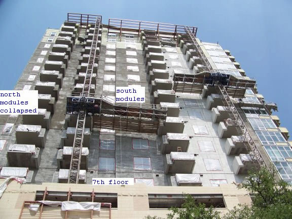
Figure 1 - Failed scaffold with north side modules separated.
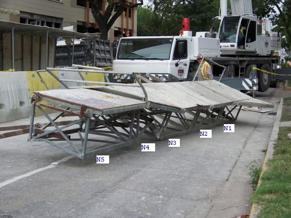
Figure 2 - Failed Deck Modules (North side)
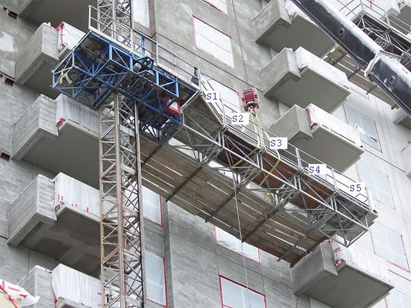
Figure 3 - Outriggers with seven walk board (south side deck modules shown)
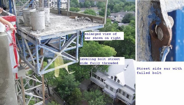
Figure 4 - Leveling Bolts and Ear on the Main Frame to which deck module #N1 was connected.
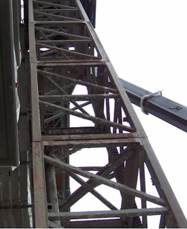
Figure 5 - Tower Mast showing non-uniform and rusted sections
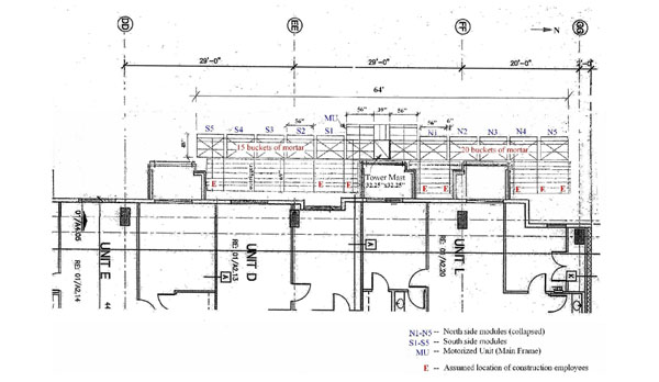
Figure 6 - Location of Platform - Prior to Collapse
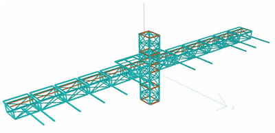
Figure 7 –STAAD Model used for Analysis
| Case Number | Loading Description | Outrigger | Deck Module | Results | |||
|---|---|---|---|---|---|---|---|
| Length | planks (udl) | Wt of employees and distance from edge of deck | Load on deck module as u.d.l. | 1.2D+1.6L Load comb. Is LRFD design satisfied? (Number of members failed) | Are members within yield stress | ||
| inch | #/ft | psf | |||||
| 1 | Design Load from Load Chart | - | - | 27 (5400/50/4) | Yes | Yes | |
| 2 | 4 times Live Load | - | - | 108 (4x27) | No (several members) | No | |
| 3 | 4 employees and 12 buckets ea. Side | 69 | 20 | 4 -200# ea side acting @ 4'6" | 10.32 (12 buckets on one side) | No ( 2 ea. side) | Yes |
| 4 | 4 employees and 20 buckets ea. Side | 69 | 20 | 4 -200# ea side @ 4'6" | 17.2 (20 buckets on one side) | No (3 ea. side) | Yes |
| 5 | 5 employees and 12 buckets ea. side | 69 | 20 | 5 -200# ea @ 4'6" | 10.32 (12 buckets on one side) | No (3 ea. side) | Yes |
| 6 | 5 employees and 20 buckets ea. side | 69 | 20 | 5 -200# ea @ 4'6" | 17.2 (20 buckets on one side) | No (3 ea. side) | Yes |
| 7 | 30" outrigger with 5 employees + design load | 30 | 20 | 5 -200# ea @ 24" | 27 (5400/50/4) | No (6 ea. side) | Yes |
| 8 | 30" outrigger with 5 employees + reduced loading | 30 | 20 | 5 -200# ea @ 24" | 17 (5400 - 10x200)/50/4 | No (1 ea. side) | Yes |
| 9 | Case 5 with street side leveling bolt removed between main frame and N1 (module #1) & between N4 and N5 | 69 | 20 | 5 -200# ea @ 4'6" | 10.32 (12 buckets on one side) | No (several members) | Yes |
| 10 | Case 6 with street side leveling bolt removed between main frame and N1 (module #1) & between N4 and N5 | 69 | 20 | 5 -200# ea @ 4'6" | 17.2 (20 buckets on one side) | No (several members) | No |
| 11 | Actual Loading at site (figure 6). street side leveling bolt removed between main frame and #N1 & between #N4 and N5 | 69 | 20 | 5 -200# ea @ 4'6" on north side 3- 200# ea @ 4'6" on south side |
17.2 (20 buckets on north side) 10.32 (12 buckets on south side) |
No (several members) | No on north side |
Figure 8
Attachment A
(Major Events from AMC Daily Service Report)Scaffold Service Record - Chronological List of major events
Based on the review of American Mast Climbers’(AMC) daily service and/or inspection reports, the following is a chronological list of major events:
- On November 19, 2008, AMC, the mast climber erector, started delivering the climber parts and the support system to the project site.
- On December 11, 2008, AMC installed 32 shoring posts with 2" laces on levels 6, 5 and 4 (Service No. 563.2). Note that the building was built with setbacks on the south side and west side at 7th floor level.
- On December 15, 2008, AMC erected Mast Climber #1 (MC #1) on I-beam base on the 7th Floor (Service No. 574.0).
- On December 19, 2008, the tower of MC #1 was 3 floors from topping out and the first tie was made for the tower of MC #2 (Service No. 574.4).
- On December 23, 2008, the tower of MC #2 topped out at 1:00 p.m. (Service No. 574.8).
- On December 30, 2008, AMC received a call from Eddie Wright of GMI to hold on setting up of MC #3 (Service No. 624.0).
- On December 31, 2008, AMC turned over both MC #1 and MC #2 to the customer (GMI). Note that both climbers were erected on the 7th floor in the south side (setback) of the building (GMI) (Service No. 625.0).
- On January 8, 2009, AMC set MC #3 on the 2' x 10' concrete pad (on ground) in the east side of the building at the south end (from Rick’s table page 2 and 6/3/09 e-mail) (Service No. 649.0).
- On January 12, 2009, the tower of MC #3 topped off (Service No. 649.4).
- On January 13, 2009, left hand side of MC #3 platform was not clear from MC #2 by 16" and ordered 1⁄2 platform from the AMC shop (Service No. 649.5). Note that from this report, MC #2 should be in the south side of the building at the east end.
- On January 19, 2009, MC #1 (in the south side of the building at the west end) had 2 broken rollers and 4 worn rollers. AMC cut out 4 roller housings, replaced 8 rollers, and 2 roller housings, and welded them back into place (Service No. 676.0). After completing the welding, AMC added more counter weight on MC #1 to limit its unbalanced deflections.
- On January 20, 2009, MC #1 was rubbing the tower and the other climber (MC #2). AMC reset the counter weights for MC #1 (3 platforms long on the left hand side and 5 on the right) (Service No. 676.1).
- On February 16, 2009, AMC performed monthly service & inspection on all three Mast Climbers. GMI signed off the inspection tickets.
- On February 16, 2009, GMI called AMC saying that “Climber (must be MC #1) is rubbing the wall and the rack lube is getting on the stone.”AMC took the climber up, pushed the second tie out to clear the building wall and went up check the rest of the ties (Service No. 724.0).
- On March 10, 2009, GMI called AMC indicating MC #2 was hitting the building wall. AMC checked and replaced rollers in both MC #2 and MC #1 (Service No. 753.0).
- On March 25, 2009, AMC replaced 4 small rollers on MC Millinium (perhaps MC #1) (Service No. 772.0).
- On April 8, 2009, MC #1 could not descend; AMC replaced the lower limit switch (Service No. 786.0).
On April 8, 2009, MC #2 and MC #3 hitting each other on the 19th floor; AMC cut the tubes and moved the MC #2 handrail 4" back (Services No. 786.1). - On April 13, 2009, all three climbers were descending slowly; AMC checked and adjusted the brakes (Service No. 797.0).
- On April 17, 2009, AMC replaced rollers on MC #2 (Service No. 804.0).
- On April 21, 2009, AMC fixed the electrical problem of MC #2 and MC #3 after the power source moved to the 6th floor (Service Nos. 805.0 and 807.0).
- On April 27, 2009, at 7:00 a.m., AMC started to dismantle MC #1 from the south side of the building at the west end, and to erect MC #1 in the west side of the building at the south end (Service No. 815.0).
On April 27, 2009, at 8:15 a.m., MC #2 stuck at the 20th floor. The extension arms bent down 10 to 12" due to too many walk boards. AMC ran (probably manually) the climber up to the temporary beam, checked all three phases of 480 volts red monitor lights, checked limit switches, and found the gate switch stuck. AMC sprayed and cycled many times and fixed the gate switch. AMC brought the climber down and repaired the walk board extensions. Then, AMC ran the climber up and down for the full travel distance two times (Service No. 825.0). - On May 4, 2009 at 9:15 a.m. AMC turned over MC #1 to the customer (GMI) at the new location in the west side. Shortly after, AMC started to disassemble the MC #2 and to shore 2 floors of a new location in the west side of the building at the north end (Service No. 823.0).
- On May 7, 2009 at 10:00 a.m., MC #1 hit the underside of the 16th floor balcony. AMC inspected the damaged. No damage at the handrail end, the component directly impacted the balcony. However, the face connection point of the first right hand platform broke at its weld. AMC fixed the weld at 5:30 p.m. and the power of the building was shut off (Service No. 833.0).
On May 8, 2009, at 7:00 a.m., AMC grinded and painted the newly weld face. GMI re- installed the handrails on six-plank wide walk boards. AMC ran the climber for the full travel distance three times, the instruments checked good and the run checked good. MC #1 was in service and ready for use by GMI (Service No. 833.0). - On May 8, 2009, AMC installed the extension arms, the walk boards (assisted GMI) and the hand rails on MC #2. AMC also ran the climber up and down for the full travel distance. MC #2 was in service and ready for use by GMI at the new location in the west side (Service No. 823.4).
- On June 4, 2009, both roller (wheel) and housing were broke at the front top right location. AMC welded the housing back and replaced with a new roller. AMC also replaced left hand side roller. AMC personnel believed that too much weight was placed on the right side of the platform (Services No. 859.0). Based on Billy Mimms’full interview statement (See Page 3, Line 30), the repaired climber should be MC #2.
- From June 8, 2009, till the day of the incident, AMC should only dismantle MC #3. Based on the project photographs, the tower sections and ties were intact for MC #1 and MC #2 prior to the incident (Service Nos. 864.0 through 864.2).
- The fatal incident occurred on June 10, 2009 at 2:20 p.m. After the incident, on June 11, 2009 at 6:30 a.m., AMC lowered the MC #1 and MC # 2 off the building (Service No. 868.0).
Attachment B
(Selected Pages from AMC Operations Manual)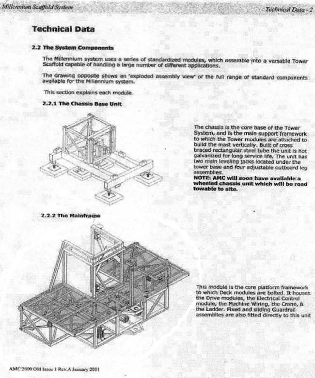
Figure 9
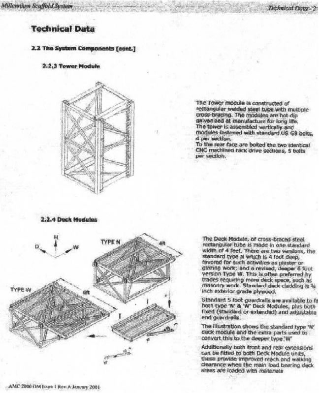
Figure 10
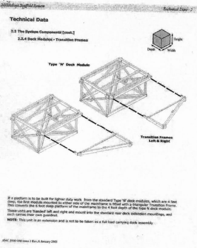
Figure 11
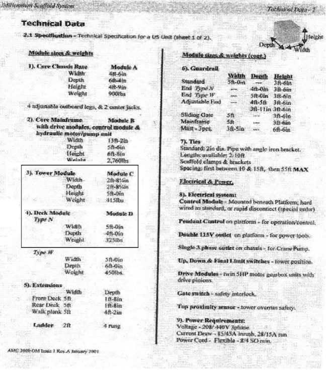
Figure 12
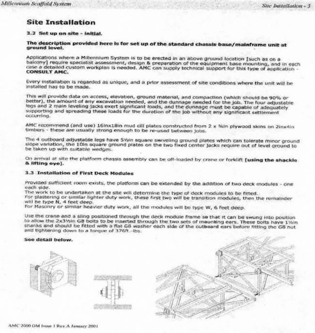
Figure 13
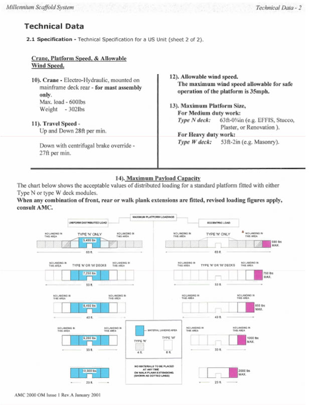
Figure 14 - Load Chart
Attachment C
(Selected drawings from Parts for Millenium Unit)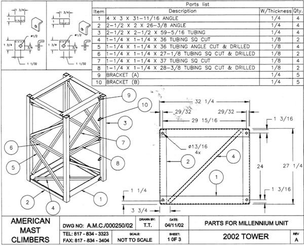
Figure 15 - Tower Mast
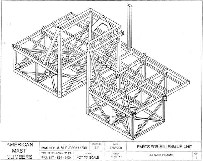
Figure 16 - Main Frame (Motorized Unit)
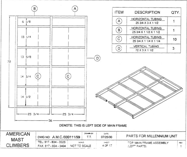
Figure 17 - Main Frame Top
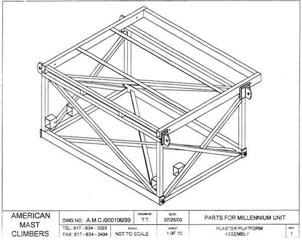
Figure 18 - Deck Module
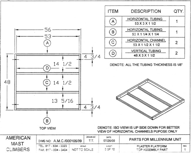
Figure 19 - Deck Module Top
Attachment D
(Relevant pages from the Report by J.E.I. Metallurgical, Inc.)36. Profile view of the hex side of the fractured SW-1 bolt is shown in Figure 21 (T020).
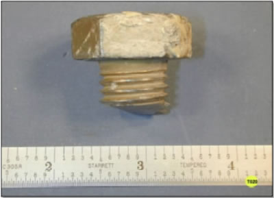
Figure 21 Profile view of the head and upper threaded portion of the (building side) SW-1 (N1) attachment bolt.
37. As can be seen in Figure 21, this bolt is fully threaded, i.e., no shank exists between the underside of the bolt hex head and the bolt threads. The fracture in Figure 21 is also noted to be relatively flat with a very small amount of bending.
38. The corresponding relatively flat fractured, "nut side" of the failed SW-1 bolt is shown in Figure 22 (T014).
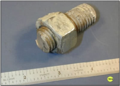
Figure 22 "Nut side" fracture of subject (N1) to motorized unit SW-1 attachment bolt. Note the fracture surface is flat with a small amount of bending.
39. A profile view of the nut side of this failed bolt is shown in Figure 23 (T013).
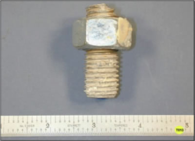
Figure 23 Profile view of the "nut side" of (N1) to (MU) motorized unit clamping bolt. This bolt was positioned on the building side of the subject platform.
40. The street side (N1) to motorized unit attachment botl also failed completely. The nut side of this fractured bolt was recovered at the scene and is shown in profile in Figure 24 (L018). This bolt fragment was denoted LH-3 by APD.
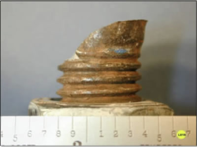
Figure 24 Profile view of street side (N1) to (MU) motorized unit attachment bolt. The threaded bolt fragment was designated LH-3 by APD.
41. In Figure 24 the LG-3 fracture surface is observed to exhibit a steeper fracture profile than the corresponding building side (N1) ear attachment bolt (SW-1).
42. A second profile view of the failed street side attachment bolt and nut is shown in Figure 25 (L010). Crushing of the nut occurred during the street side (N1) ear deformation and the bolt head entrapment process.
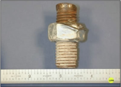
Figure 25 Rotated view of street side (N1) to (MU) motorized unit attachment threaded bolt fragment. Note nut deformation and crushing of the threaded bolt fragment.
43. A persprective view of LH-3 bolt is shown in Figure 26 (L019).
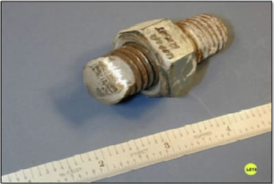
Figure 26 Perspective view of LH-3 threaded bolt fragment.
44. A close-up profile view illustrating that this bolt is a "shanked" bolt is shown in Figure 27 (L018). The direction of shear force and shank deformation are noted.
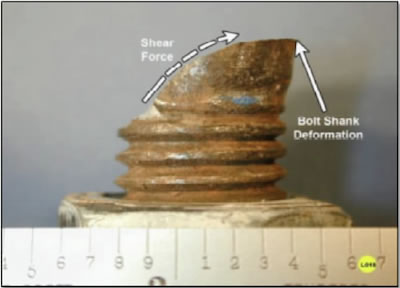
Figure 27 Profile view of LH-3 (N-1) street side bolt failure. The direction of shearing force and bolt shank deformation are noted.
45. The hex head side of the street side (N1) attachment bolt was captured (embedded) in the (N1) street side ear at the time of the accident. An overall view of the (N1) trapezoidal platform scaffold, with the street side ear and captured failed bolt denoted is shown in Figure 28 (A138).
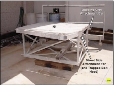
Figure 28 Overall view of the (N1) trapezoidal platform stored at M&M Engineering Associates, Inc. The street side attachment ear and embedded bolt are noted.
46. Closeup views of the embedded and captured hex head fractured bolt are shown in Figures 29 (A145) and 30 (A146). Head markings in Figure 20 indicate that the bolt is Grade 8.
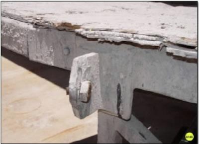
Figure 29 Perspective view of the trapped/ embedded hexagonal bolt head in the street side attachment ear.
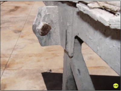
Figure 30 Normal view (from the building side toward the street side) of the trapped/embedded hexagonal bolt head in the (N1) attachment ear. Bolt head markings indicate that the bolt is a Grade 8 bolt.
47. The attachment ear (and embedded bolt head) shown in Figures 29 and 30 were cut from the (N1) scaffold section and the embedded bolt head was retrieved for detailed laboratory examination.
48. An embedded hex head bolt fragment after being released from the deformed ear is shown in Figure 31 (e001).
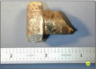
Figure 31 Profile view of the embedded hex head bolt fragment after being released from the deformed attachment ear.
49. A Closeup view of the hex head side fracture surface of the LH-3 hex head bolt is shown in figure 32 (e012). The final fracture area and fracture origin areas are denoted in Figure 32.
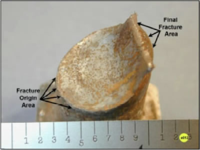
Figure 32 Closeup view of hex head bolt fracture. The final fracture adn fracture origin areas are noted.
Scanning Electron Microscopy
50. As indicated previously, the street side ear attachment bolt was designated LH-3. The LH-3 nut side of the fracture was examined in the SEM.
51. An overall view of the LH-3, nut side fracture surface, is shown in Figure 33 (L016).
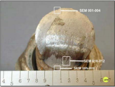
Figure 33 Overal view of LH-3 "nut side" fracture surface. Areas where SEM examination were conducted are noted.