
Investigation of the March 23, 2015 Mast Climbing Scaffold Collapse during Dismantling at Raleigh, NC
Summary Statement
This report describes the engineering investigation of a fatal mast climbing scaffold collapse that was conducted by OSHA’s Directorate of Construction in collaboration with the North Carolina Department of Labor. It includes interviews, photographs, analysis of the incident, and structural analyses. It concludes that the cause of the failure of the mast climbing platform was the excessive free standing height of the mast and higher magnitude of loads placed on the platform than permitted by the manufacturer, improper erection of the mast climbing platform and its mast, and bolt failure, and failure to comply with OSHA regulations 1926.451(a)(1).
August 2015
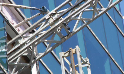
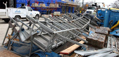
TABLE OF CONTENTS
- Introduction
- Description of the Mast Scaffold
- Participants of the Project
- Description of the Project
- Description of the Incident
- Structural Analyses and Discussion
- Conclusions
- Appendix
LIST OF FIGURES
- Fig. 1 Mast sections bolted with swing bolts
- Fig. 2 Mast sections bolted with swing bolts
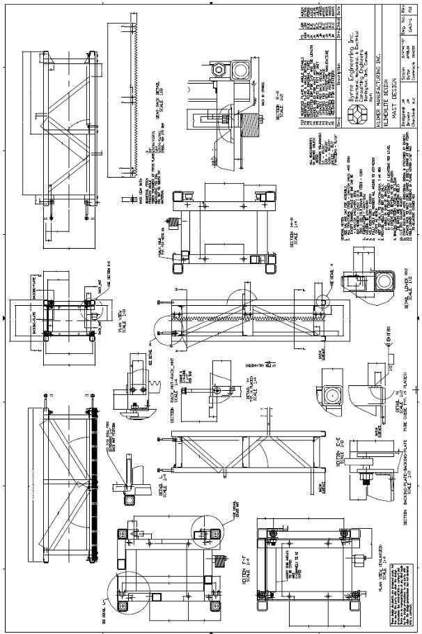
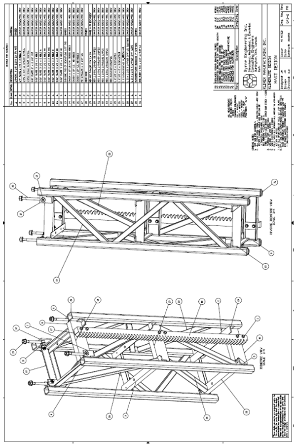
- Fig. 3 Mast design drawing (provided by manufacturer)
- Fig. 4 Mast design drawing (provided by manufacturer)
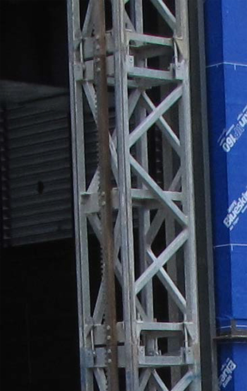
- Fig. 5 Mast section
- Fig. 6 Mast section plan
- Fig. 7 Participants of the project
- Fig. 8 Location of mast-climbers #3 and # 4 (south side)
- Fig. 9 Location of mast-climbers #5 and #6 (west side)
- Fig. 10 Location of mast-climbers #1 and # 2 (east side)
- Fig. 11 Mast sections and platform on the ground after collapse
- Fig. 12 Mast sections on the ground after collapse
- Fig. 13 Mast sections from floors 6 to 9 after collapse
- Fig. 14 Collapsed platform deck lying upside down
- Fig. 15 Location of separation of mast sections
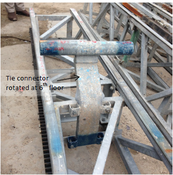
- Fig. 16 Mast sections at 6th floor rotated
- Fig. 17 Mast sections at 6th floor rotated
- Fig. 18 Mast sections at 6th floor after collapse
- Fig. 19 Mast sections at 6th floor after collapse
- Fig. 20 Mast sections at 6th floor after collapse
- Fig. 21 6th floor ties
- Fig. 22 Top of section that remained up straight
- Fig. 23 Mast section that was hanging at 6th floor
- Fig. 24 Load Chart for Single-Mast layout from manual
- Fig. 25 Load Chart displayed on a Mast
- Fig. 26 Mast scaffold nearby showing the extended upper deck and lower deck
- Fig. 27 Collapsed Mast scaffold deck lying on the ground upside down
- Fig. 28 Mast scaffold platform plan
- Fig. 29 STAAD model for analysis
- Fig. 30 Location of removed mast sections on the platform assumed for analysis
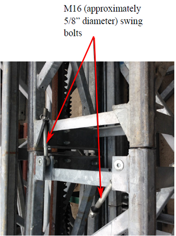
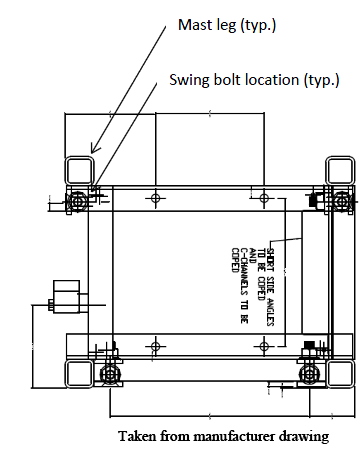
- Fig. 31 Plan showing swing bolt location
- Fig. 32 Analysis Results
- Fig. 33 Bolt punched through ¼” plate
- Fig. 34 Bolt punched through ¼” plate
- Fig. 35 Bolt punched through ¼” plate
- Fig. 36 Bolt punched through ¼” plate
Introduction
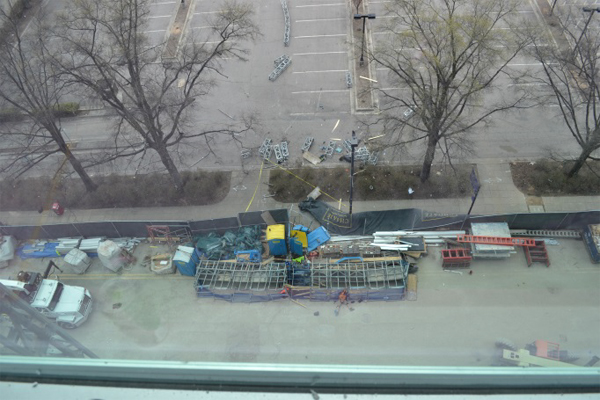
A 12-story steel framed building with concrete floor slabs was under construction at Charter Square, 501 Fayetteville Street, Raleigh, NC. The exterior of the building was to be clad with glass curtain walls. The construction was almost complete on March 23, 2015 when during the disassembly, one of the masts climbing work platforms collapsed at approximately 11:00 a.m. The mast supporting the platform partially collapsed. At the time of the incident, there were four employees on the platform perched near the 9th floor. All four fell to the ground with the falling mast and platform. Three were killed and the fourth fell on the roof of a portable toilet, and suffered severe injuries.
The North Carolina Department of Labor contacted the Directorate of Construction (DOC) in the OSHA National office, Washington, DC, to request engineering assistance in determining the cause of the collapse, and to evaluate whether OSHA and industry standards had been violated. Two structural engineers from DOC visited the site to examine the failed mast climbing platforms and its mast, and to obtain documents, interview key personnel, take photographs, and take necessary measurements.
The DOC investigation included a review of drawings, the manufacturer’s manual, relevant industry standards, and an independent structural analysis of the mast under different loading conditions. The following is our report.
Description of the Mast Scaffold
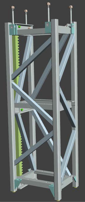
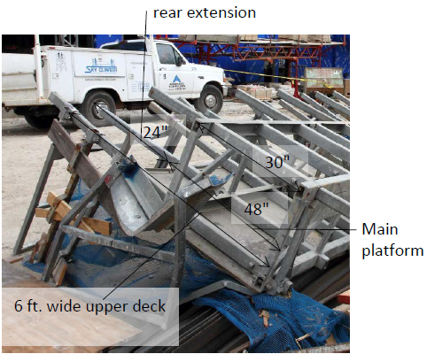
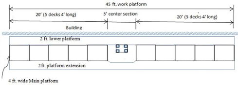
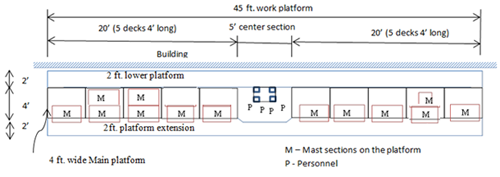
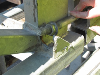
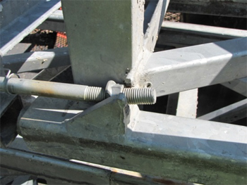
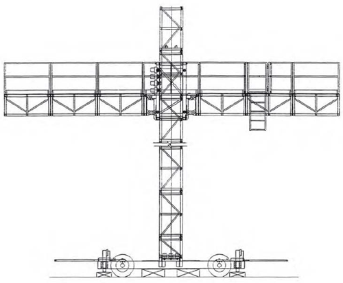
There was a 45 ft. long, 6 ft. wide (4 ft. wide main platform plus 2 ft. wide extension) work platform, which traveled up and down the rectangular mast to the desired location of activity by means of a drive system attached to the mast. The platform consisted of five deck sections, each 4 ft. long on either side of the mast. The center section of the platform containing drive units was 5 ft. long. The mast’s outside dimension was 20”x 16”. The longer dimension was parallel to the building. The four corner masts consisted of 2x2x3/16” steel tubes braced with diagonal tubular sections, 1 ½”x 1 ½” on all four sides. The diagonal bracings were concentric on two sides and off center on the other two sides. The mast was braced for lateral stability at certain floors of the structure by three ties, two at approximately right angles to the face of the building, and one diagonally to resist torsional forces. The mast consisted of 5 ft. high sections seated at the top of each other, and bolted together with spring loaded bolt located on the lower section of the mast, see Fig. 1 and 2. The bolts were connected to an outstanding flange of a steel angle welded to the mast at the upper section and the steel angles were welded to the mast but in the opposite direction. See Fig. 3 thru 6 for mast design drawings.
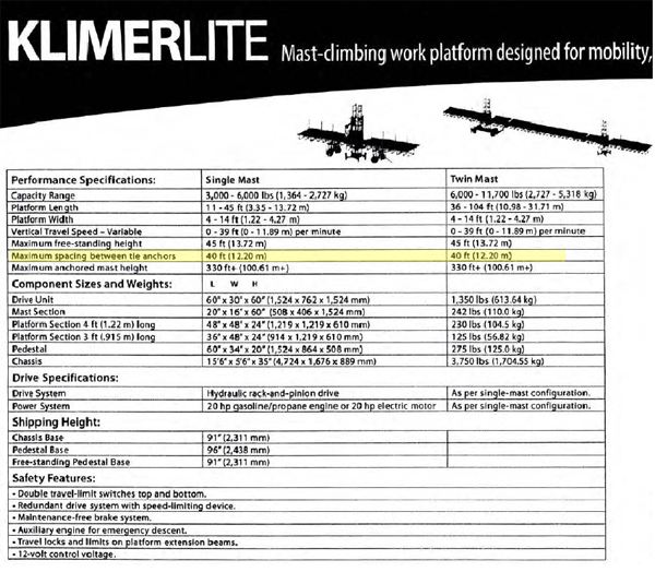
A load table was provided by the manufacturer that stated that a maximum of 1,500 pounds could be placed on either side of the mast uniformly distributed over the main deck with a total load of 3,000 pounds over the entire 45 ft. long platform. The table does not permit loads of the materials to be placed over the two ft. extension, but personnel could stand on the extended platform. It further specifies that the maximum vertical spacing between the lateral ties to be 40 ft. that also establishes the free standing height during dismantling not to exceed 40 ft. During the dismantling process, the maximum load that can be placed on the platform was also 3,000 pounds over a 45 ft. long deck without upper rear extension. The length of the deck need not be shortened during dismantling.
Participants of the Project
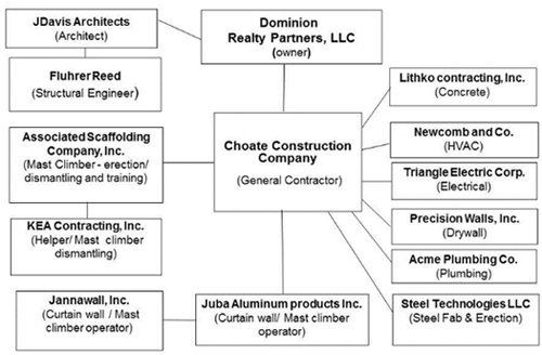
The following were the principal participants of the project:
Dominion Realty Partners, LLC – Owner
JDavis Architect - Architect
Choate Construction Company – General Contractor
The General Contractor had several subcontractors working on the project, see Fig. 7, below.
Description of the Project
Choate Construction Company (Choate) awarded the contract to Associated Scaffolding Company, Inc. (Associated) to install six mast climbing platforms in December 2014. Associated owns, leases, erects and disassembles mast-climbers at construction sites. Associated decided to use a mast-climber model called “Klimerlite” manufactured by Klimer Platforms Inc. of Milton, Ontario, Canada. Associated acquired the Klimerlite units from the manufacturer in 2007 including the base, drive units, mast sections, platform sections, ties, guard rail, swing bolts and nuts. It was later discovered after the incident that some of the ties laterally supporting the mast to the building structure were not the original ties purchased from Klimer but this did not contribute to the incident.
The original purpose of erecting mast climbers was to perform stud framing, detail work, metal panel work and the soffit of the overhang of the roof, called the roof wing on the east, south and west faces of the building. It was, however, reported that a decision was later made to install some glass windows from the mast climbing platforms at the higher floors of the building as it was considered convenient and expedient. At the lower floors, swing stage scaffolds were used to erect the glass curtain walls.
Description of the incident
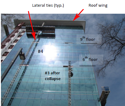
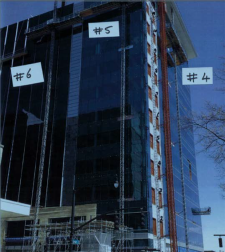
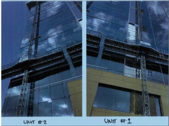
Associated erected six mast-climbers; Tower Nos. 1 & 2 on the east face, Nos. 3 & 4 on the south face and Nos. 5 & 6 on the west face of the building under construction, see Fig. 8, 9 and 10. No mast-climber was erected on the north face as there was no “roof wing” on the north face. After the mast climbers were erected by Associated at the construction site, the mast climbers were then leased to Choate, who was assigned the job of operating them during the construction period. Associated provided training to the employees of Choate and another contractor, Jannawall, Inc., to operate the mast climber. Jannawall was erecting the glass panels for the curtain walls of the building under construction. After the erection of the mast climber was completed, and training provided to the employees who would operate them, Associated left the construction site. Associated was responsible for assembling and disassembling the tower, but not to operate the platform during construction. Associated would later be called upon by Choate to disassemble them. Tower No. 3 was the first to be disassembled by Associated. This tower failed during its disassembly process. This report will confine itself to Tower No. 3. The rest of the towers were to be disassembled by Associated, and they were standing upright in their original configuration at the time of the failure of Tower No. 3. The failure of Tower No. 3 did not impact any other tower.
One of the most critical considerations in the stability of the mast climber is the frequency and location of the lateral ties of the mast. Associated, in consultation with Choate, decided to tie the mast of the Tower No. 3 at the 3rd, 6th, 9th and 11th floors and to the steel framing midway between the main roof and the roof wing. The spacing between the ties is given below:
Spacing between the 3rd and 6th floor ties: 47 ft.
Spacing between the 6th and 9th floor ties: 47 ft.
Spacing between the 9th and 11th floor ties: 31 ft.
Spacing between the 11th and roof ties: 25 ft.
As can be seen, from the time of assembly, the distance between the ties did not conform to the manufacturer’s recommendation not to exceed 40 ft. The mast cantilevered approximately 12’-8” (two 5’ high sections and one 2’-8” high section) above the last tie.
Associated had two certified technicians, David Raper (David) and Elmer Guevara (Elmer) for assembling and disassembling the mast climbers. Associated assigned David Raper to assemble the tower. He had extensive experience in erecting and disassembling swing stage scaffolds and mast climbing platforms. He assembled the tower without any apparent difficulties. It took him approximately an hour to erect the tower between the ties. He provided ties on the 3rd, 6th, 9th, 11th floors and on the roof level as was agreed between Associated and Choate. There were three ties at each floor. The connections between the vertical mast sections were made by bearings and by spring-loaded bolts, which were torqued, to the new specification of 125-130 ft. pounds by using a torque wrench. The reduced amount of torque to be applied to the bolts was provided by the manufacturer. The original torque was 225 ft. pounds. The tower was plumbed by adjusting the turnbuckle at the ties. Decks, extensions planks, and handrails were added. David Raper trained a number of Jannawalls’ employees to operate the platform. Jannawalls’ employees were also directed by David to refer to the manual placed near the blue box.
On March 23, 2015, Associated asked the other certified technician, Elmer Guevara, to dis-assemble tower No. 3 as David Raper was busy doing other assignments. Elmer was accompanied by Mr. Anderson Almeida, aka “Brazilian” who was hired by Associated on a temporary basis from KEA Contracting, Inc. Elmer and Almeida had worked together on other projects in the past. Elmer was quite familiar with the construction site as he had installed tower mast Nos. 1, 2, 4 and 6. The other technician, David Raper, had installed tower Nos. 3 and 5.
Elmer and Almeida began to remove tower sections from above the topmost roof ties. They placed the three disassembled sections on the platform and then removed the ties at the roof level. They then proceeded to remove the five mast sections between the roof and the 11th floor ties. All of the removed mast sections were placed on the platform deck. They then removed the ties on the 11th floor, and thereafter they began to remove the five mast sections proceeding down to the 9th floor. In total, they removed thirteen sections down to the 9th floor tie. The 13 disassembled sections and 6 ties were placed over the mast climbing platform deck. At this stage, Elmer decided not to proceed to the ground to unload the 13 removed sections and the ties, and then to come up to the 9th floor to continue with the disassembly process. Elmer decided to continue the disassembly process without unloading the sections and the ties. This would later prove to be a fateful decision. There were two other employees on the deck in addition to Elmer and Almieda. The other two were employed by Jannawall: Jose Lopez-Ramirez and Jose Claros-Hernandez.
In preparation for disassembling the tower section from the 9th to the 6th floors, the ties at the 9th floor were removed from the concrete floor slab inside the structure. The next step was to remove the ties from the mast before proceeding to remove the mast sections. At that instant, the tower leaned away from the building and collapsed on the ground.
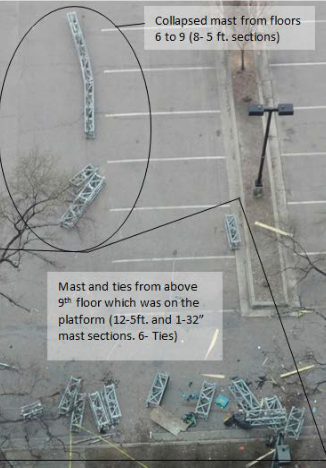
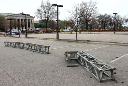
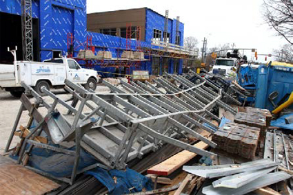
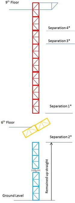
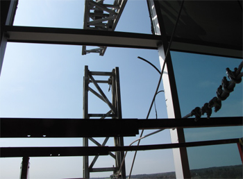
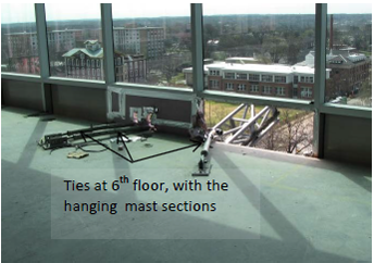
Three employees were thrown to the ground and were killed. The fourth employee, Elmer, fell over the roof of a portable toilet and was saved. The standing mast from the 6th to the 9th floor fractured five feet above the 6th level, and five feet below the 6th floor, and fell to the ground in three parts. One part contained five sections (5x5=25 ft.) still connected to each other. The second part consisted of two sections (5x2=10 ft.) and the third part was a solitary section (5 ft.). These parts fell farthest from the building. The 13 sections and the 6 ties, which were placed over the deck, fell in a scattered manner to the ground; see Fig. 11, 12 and 13. The 45 ft. long deck fell almost intact, lying closest to the building, see Fig. 11 and 14.
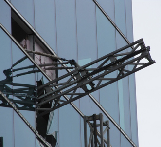
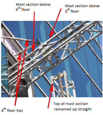
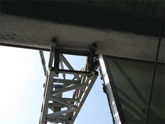
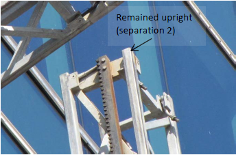
The two sections, one above the 6th floor and the other below the 6th floor, were still connected to each other but were leaning approximately 45 degrees. These two sections remained connected to the 6th floor ties, see Fig. 15 thru 23.
Structural Analyses and Discussion
The purpose of the Structural Analysis was to examine the stability of the mast standing freely from the 6th floor up to the 9th floor without any lateral supports. The most critical elements for stability are the unsupported height of the mast, the total loads placed over the platform, the lateral loads applied to the platform, the actual position of the superimposed loads on the platform, the ability of the swing bolts to resist tension, the magnitude of pretension in the bolts, and the P-delta effect.
The unsupported height of the mast was 47 feet, the distance between the 6th and the 9th floor. The total superimposed load placed on the platform was 4,260 pounds as detailed below.
| Weight of 13 mast sections (12-5' sections and 1-2'-8" section) | = 3,070 lbs. |
| Weight of 6 ties (3 ties weigh 200 lbs) | = 400 lbs. |
| Weight of 4 employees = 175 lbs x 4 | = 700 lbs. |
| Weight of personal equipment for first two persons | = 90 lbs. |
| Total gravity load on the platform | = 4,260 lbs. |
| Total lateral load on the platform, as per ANSI | = 135 lbs. |
| Notes: Weight of a 5 ft. tall mast section was 245 lbs. Employees weight was 175 pounds, as per ANSI standard. Equipment weight was 45 pounds for the first two employees. No equipment weight was taken for the other two employees. Lateral loads were 45 pounds for the first two employees, and 22.5 pounds for the remaining two employees, as per ANSI standard. The lateral loads were applied at the platform, and not at the height of 42 inches above the platform as required by ANSI. An additional weight of 1,300 pounds was assumed for the motorized unit. Weights of the planks on the deck, on the upper and lower extensions, were ignored. For the connections, 10% of the weight was added. | |
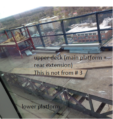
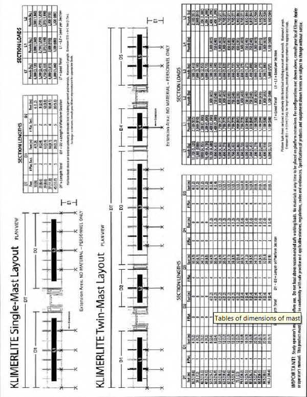
According to Klimer, the allowable load on the Klimerlite single-mast for a free-standing height of 40 ft. with a 45 ft. long platform without upper rear extension was 3,000 pounds which included the weight of employees. The 3,000 lbs. had to be evenly distributed on each side of the main platform with a maximum of 1,500 pounds per side, see Fig. 24 and 25, load chart. The 3000 pounds allowable load is valid only for standard configuration for a 45 ft. long platform with extensions up to 5 feet on the wall side (lower platform) and no rear extension.
The load chart states “IMPORTANT! Study operator's manual before use. Do not load above recommended safe working loads. No materials at any time to be placed on platform extensions. For configurations not shown above, consult your local Kilmer dealer or operator's manual. This product must be used in conformity with safe practice and applicable statutes, regulations, codes and ordinances. Specifications of products and equipment shown herein are subject to change without notice.”
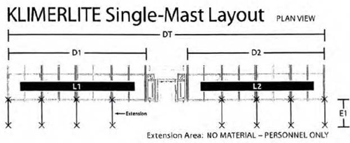
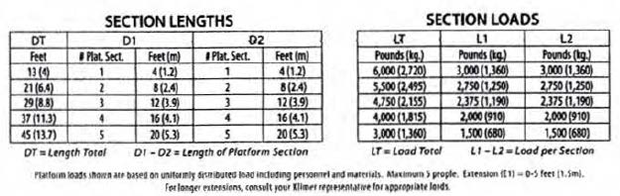
Fig. 24 - Load Chart for Single-Mast layout from manual
Klimer, during OSHA’s interview, confimed that the uniformly distributed load of 3,000 pounds was valid for both operating and dismantling the mast climbing platform with a maximumm height of 40 ft.
The failed mast climbing scaffold had a front lower extension of 24" and a rear upper extension of 24", see Fig. 26, 27 and 28. The dead weight of the rear extension (extension steel tubes and deck) itself is approximately 500 lbs. The deck with an upper extension is not a standard configuration and is not commonly used in the industry. All manufacturers generally do not provide the safe capacity of the deck configuration with the upper rear deck, and ask that the user contact them to determine the safe load capacity. In this instance, the manufacturer was not contacted to determine the safe load carrying capacity of the deck configured with an upper rear deck. The safe load carrying capacity will be lower than 3,000 pounds and if the load is placed on the rear extension, the allowable load capacity will be further reduced due to the greater eccentricity of the loading. It is not known whether the contractor was using the rear extension as a part of the main platform during dismantling and whether the dis-assempled mast sections were actually placed on the rear extension area.
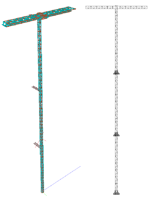
STAAD.Pro program was used to create a 3-D model of the mast along with the platform for the analysis, see Fig. 29. Since the incident occurred during dismantling, analysis was performed for the dismantling condition only. In the STAAD analysis, the bolts were assumed to be at the center line of the mast legs. The roller mechanism on the mast was not included in the model.
Four cases were considered and a P-delta analysis was performed. Wind was not considered in the computation.
The location of the superimposed loads is discussed under each case below. Four cases were considered and the superimposed loads were assumed to be placed on the main platform deck. The first case, Case I, considered the ideal situation where the free-standing height of the mast was limited to 40 ft., and the superimposed load was limited to 3,000 pounds uniformly distributed on the main deck, and not on the extensions. The second case, Case II, was similar to the first case except the free-standing height was increased to 47 ft. instead of 40 ft. The third case , Case III, was to replicate the actual conditions as they existed at the time of the incident, i.e., height increased to 47 ft. and gravity load increased to 4,260 pounds. In this case, the superimposed load of 4,260 pounds was assumed to be distributed in an ideal manner, i.e., uniformly distrubuted over the entire main deck on both sides, though it is highly questionable that this was even possible given the fact that the crew wanted to load additional mast sections by continuing to dismantle the mast from the 9th to the 6th floor. The fourth case, Case IV, was identical to Case III except the distribution of the superimposed load was considered in a more practical way considering the difficuties involved in dragging the sections across the 45 ft. long deck, and making room for additional sections to be placed on the deck.
Case I – As per manufacturer’s recommendation:
- Maximum distance between ties: 40 feet
- Load on the platform: 3,000 lbs. distributed uniformly along the main platform which includes the weight of people.
- A horizontal load of 135 lbs. as per ANSI/SIA A92.9-2011
- Mast cantilever height: 40 ft.
Case II –
- Load on the platform: 3,000 lbs. distributed uniformly along the main platform
- A horizontal load of 135 lbs. as per ANSI/SIA A92.9-2011
- Mast cantilever height: 47 ft.
Case III –
- Total load on the main platform including people and personal equipment 4,260 lbs. (as calculated above) uniformly distributed in an ideal condition.
- A horizontal load of 135 lbs as per ANSI/SIA A92.9-2011
- Mast cantilever height: 47 ft.
Case IV –
- Identical to Case III but the distribution of loads was not uniform.
- Mast sections location on the main platform were based on expediency and practical considerations, as shown in Fig. 30.
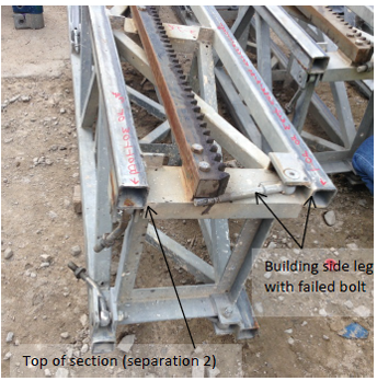
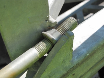
As stated earlier in this report, the mast sections were placed over each other with the gravity loads being transferred by bearing and through four M16 (approximately 5/8” diameter) swing bolts, one at each post, approximately 8” long, with a grooved nut-washer. The bolts were fastened to the lower mast section and engaged the top sections by a nut. The nut sits on the outstanding flange of a steel angle that had a U shaped cut-out opening to receive the bolt. The 1/4” thick steel angle was welded to the mast posts. The bolts were torqued to a force of 125 ft.-lbs. as per direction given by the manufacturer. Previously, the designated torque value was over 200 ft.-lbs. which was later reduced to 125 ft.-lbs. The torques induced a pretension in the bolts calculated to be approximately 12,000 pounds.
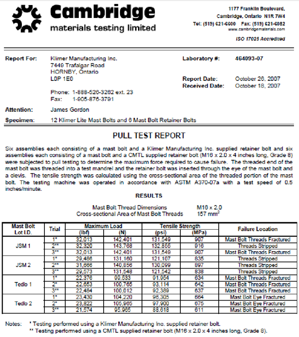
The manufacturer provided OSHA the “pull test report” of the retainer swing bolts (M16x2.0x4 inches long, Grade 8) conducted in 2007, and from the report the bolt threads fractured at a load of 22.5 kips, see Appendix.
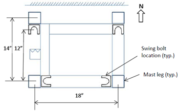
In the computer model, the distance between bolts were 14” in the N-S direction and 18” in the E-W direction. The actual distance, however, between the bolts in the N-S direction was approximately 12”, see Fig. 31, which will increase the tension in the bolt by 17%.
In our computations, see Fig. 32 below, we did not acount for the increase in tension due to reduced spacing of the bolts in the N-S direction.
| Summary of forces on mast climbing main support legs | |||||||
|---|---|---|---|---|---|---|---|
| Case number | Free standing height of the mast (feet) | Horizontal load applied to the mast (pounds) | Superimposed load on the mast (pounds) | Tension (kips) | Compression (kips) | P-Δ effects taken into account? | Remarks |
| I | 40 | 135 | 3,000 | 5.0 | 11 | No | |
| 6.75 | 13 | yes | |||||
| II | 40 | 135 | 3,000 | 5.2 | 11 | No | |
| 7.25 | 13 | yes | |||||
| III | 47 | 135 | 4,260 | 5.38 | 12 | No | |
| 8.7 | 15 | yes | |||||
| IV | 47 | 135 | 4,260 | 8.0 | 14 | No | |
| 12.0 | 18 | yes | |||||
At the time of the incident, the mast sections and ties above the 9th floor were already removed and the platform was at the 9th floor level. When the employees disconnected the ties from the 14” 18” 12” N Swing bolt location (typ.) Mast leg (typ.) support at the 9th floor, the mast had a overall height of approximately 135 feet, with the ties attached at the 3rd and 6th floors. The spacing of the ties between the 3rd and 6th floor ties was 47 ft. and the mast above the 6th floor cantilevered for the same height of 47 ft.
OSHA 1926.451(a)(1) states that “Except as provided in paragraphs (a)(2), (a)(3), (a)(4), (a)(5) and (g) of this section, each scaffold and scaffold component shall be capable of supporting , without failure, its own weight and at least 4 times the maximum intended load applied or transmitted to it.”
For Case I, for a free-standing height of 40 ft. and with a load of 3000 lbs., uniformly distributed over the entire deck, the two bolts on the side of the building near the 6th floor were subjected to a tension of approximately 5 kips, which can be increased by 17% to adjust for the actual location of the bolts in the N-S direction. With consideration of pre-tension in the bolt, and adjusting for the actual spacing between the bolts, the net tension in the bolt was approximately 18 kips. With P-delta effect and the pre-tension, the tension was increased to approximately 20 kips below the failure load of 22 kips. Hence, the mast could safely support 3,000 pounds when uniformly distributed for a cantilevered height of 40 ft. However the capacity of the bolt did not comply with OSHA’s regulations, mentioned above. OSHA regulations 29 CFR 1926.451(a)(1) was not satisfied regardless of whether the safe capacity of the deck was taken as 3,000 or 2,000 pounds.
For Case II, which is identical to Case I except for a cantilevered height of 47 ft. the tenson in the bolts on the side of the building near the 6th floor was not significantly changed. The tension changed to 5.2 kips from 5 kips. With consideration of the actual spacing of the bolts, and p-delta effect, and pre-tension, the tension in the bolts increased to approximately 20.5 kips. Thus the mast could support 3,000 pounds uniformly supported for a free-standing height of 47 ft. However the capacity of the bolt did not meet OSHA’s regulations mentioned above. OSHA regulations 29 CFR 1926.451(a)(1) was not satisfied regardless of whether the safe capacity of the deck was taken as 3,000 or 2,000 pounds.
For Case III, for a cantilevered height of 47 ft. with a load of 4,260 lbs. uniformly distributed, the tension in the bolts on the side of the building near the 6th floor level increased only slightly to 5.8 kips. Considering the P-delta effect, the reduced spacing between the bolts and the pre-tension, the tension in the bolts was approximately 22 kips, close to the failure load. It must be mentioned here that the loading and the height of the free-standing height of Case III exceeded the permissible limit set by the manufacturer.
For Case IV, which was identical to Case III except for the fact that the superimposed load on the platform was not uniformly distributed, but as shown in Fig. 30, the tension in the bolts significantly increased to 8 kips. Again with due consideration of the P-delta effect, and the reduced spacing between the bolts and pre-tension in the bolts, the tension in the bolts was 26 kips, well above the failure load, and this caused the failure.
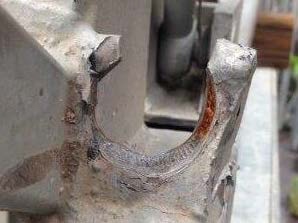
It is interesting to note that in the remnants of the mast stored in the yard of Associated Scaffolding Inc., a swing bolt was discovered to have punched through the 1/4” outstanding flange of the steel angle, see Fig. 33 thru 36. Our calculations indicated that the punching shear capacity of the leg of the angle was approximately 25 kips, though it is not certain whether that was the triggering mechanism or it happened during the collapse.
We highly recommend that the design of the mast climbing platform be brought into compliance with the above stated OSHA regulations 1926.451(a)(1). Reducing the distance between the lateral ties to 20 ft. from the present 40 ft. should be examined to determine if it could result in compliance with the OSHA regulations.
Conclusions
- The cause of the failure of the mast climbing platform was the excessive free standing height of the mast and higher magnitude of loads placed on the platform than permitted by the manufacturer. The actual freestanding height of the mast was 47 feet against the allowable 40 ft. and the loads placed on the platform were approximately 4,260 pounds much higher than the allowable 3000 pounds. The allowable load would be even lower with the upper rear extension. The combination of these two factors resulted in the failure. The contractor thereby violated OSHA regulations 29 CFR 1926.451(f)(1) “Scaffolds and scaffold components shall not be loaded in excess of their maximum intended loads or rated capacities, whichever is less.”
- The erection of the mast climbing platform and its mast was improperly done as the vertical spacing of the lateral ties exceeded the manufacturer’s maximum permitted height of 40 ft. This contributed to the collapse. Thus, OSHA regulations 29 CFR 1926.451(c)(1)(ii) “Guys, ties, and braces shall be installed according to the scaffold manufacturer's recommendations …” was violated.
- The failure of the swing bolts near the 6th floor connecting the lower and upper sections of the mast triggered the failure.
- The dismantling of the mast climbing platform and its mast was done improperly as the technician overloaded the platform, which was further exacerbated by untying the 9th floor ties. The technician should have unloaded the dis-assembled sections to the ground, and then come up to untie the 9th floor ties.
- The mast climbing platform erected was of a non-standard configuration because of upper rear platform, and the contractor did not consult the manufacturer to obtain the corresponding load chart for the modified configuration. The contractor operated the mast climbing platform with an improper load chart. This contributed to the collapse.
APPENDIX
(Pull Test report and extract from Klimerlite manual)
OPERATORS INSTRUCTION MANUAL
KlimerLite Mast Climbing Work Platform
Imperial Version, ISO 16369, ANSI 92.9
Revised October 15, 2005
| Wights (approximate): | |
|---|---|
| Chassis | 3750 lbs |
| Chassis with drive unit | 5150 lbs |
| Drive unit | 1350 lbs |
| Platform | 240 lbs |
| Mast | 250 lbs |
| Pedestal | 275 lbs |
| Railing | 50 lbs |
IMPORTANT
- STUDY OPERATOR'S MANUAL BEFORE USE.
- DO NOT LOAD ABOVE RECOMMENDED SAFE WORKING LOADS.
- WHEN MACHINE IS ASSEMBLED WITH DECKS NOT EQUAL, (MAX 4' DIFFERENCE), ALWAYS USE HIGHEST NUMBER TO DETERMINE MAXIMUM LOAD. IN THE CASE OF 4 VS 3 ASSUME 4 DECKS PER SIDE AND LOAD WOULD BE 4000 LBS.
- NO MATERIALS AT ANY TIME TO BE PLACED ON PLATFORM EXTENSIONS.
For twin-mast and all other configurations not shown, contact your Klimer Representative Maximum platform extension: 5 ft. (1.5 m).
U.S. Department of Labor
Occupational Safety and Health Administration
Directorate of Construction
August 2015
Report Prepared by
Mohammad Ayub, P.E., S.E.
Office of Engineering Services
Directorate of Construction
Contributions to this report by
Scott Jin, Ph.D., P.E.
Dinesh Shah, P.E.
Gopal Menon, P.E.
Directorate of Construction
Belvin Horres
Jeff McClaren
Kathy D. Capps
Office of NC Department of Labor
Investigation of the March 23, 2015 Mast Climbing Scaffold Collapse during Dismantling at Raleigh, NC